
This technical article was written by Osmay Oharriz, MSc., Technical Manager, Belzona, and was published by Hydrocarbon Processing. Part 1 is available here.
Most industrial assets operating at elevated temperatures require thermal insulation for energy conservation, thermal protection or process stabilization. As soon as the insulation is installed and in service, the risk of the underlying substrate of suffering from corrosion under insulation (CUI) increases. It should be noted that CUI represents a severe threat to the onstream reliability of many of today’s refining, chemical, power generating, and pulp and paper industries, including onshore and offshore installations.
The mechanism of CUI is initiated by the ingress of water into the thermal insulation, which traps the solution at the annular space between the metal substrate and the insulation. As a result, the substrate starts corroding under the insulation. Elevated temperatures exacerbate this corrosion mechanism.
NACE SP0198 defines carbon steel, austenitic and duplex stainless steels as the primary metallic substrates potentially suffering from CUI. In practice, CUI commonly appears in thermal ranges between 50°F (10°C) and 350°F (177°C), or where there is cyclic operation of the equipment. For carbon steels, CUI manifests in the form of uniform and localized corrosion. For austenitic and duplex stainless steels, CUI is normally localized, leading to stress corrosion cracking if appropriate environmental conditions and stress levels are met.1
Part 1 of this article detailed the development of a novel epoxy closed-cell foam insulating and corrosion protection barrier by a coating manufacturer. Design considerations of such a material, fitness-for-service testing and results were also presented. Potential application areas and benefits, including worksite personnel and CUI protection, were discussed.
Experimental Procedure
Thermal conductivity (EN 12667/ASME C177).
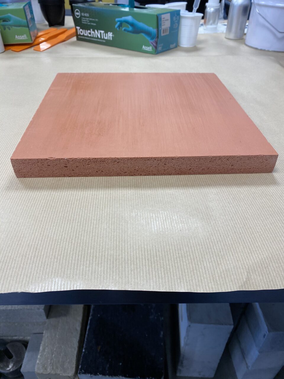
Thermal conductivity is used to measure the ability of a material to conduct heat when in thermal contact with another surface. Two samples of the proprietary epoxy foama were cast and allowed to grow at ambient temperature, as shown in FIG. 4. The samples were sandwiched between a central heating slab (hot plate) and two peripheral flat cooling slabs (cold plates) in a guarded box, as depicted in FIG. 5.
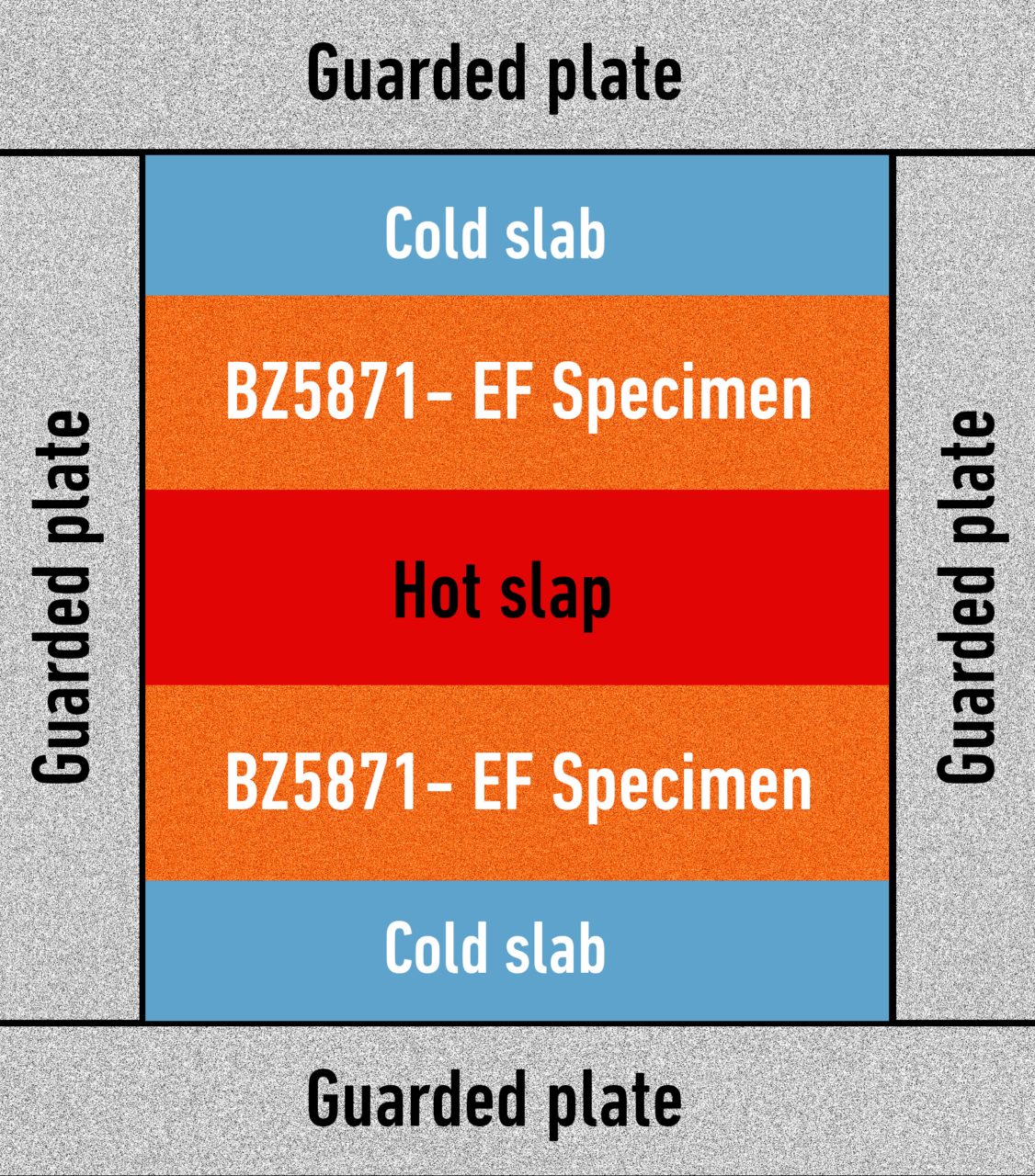
Heat was generated and the temperatures of the sample surface adjacent to both the hot and cold slabs were measured and averaged. The thermal conductivity of the epoxy foam was then calculated based on one-dimension heat transfer equations at sample mean temperatures of –40°F (-40°C), –4°F (-20°C), 32°F (0°C), 68°F (20°C), 140°F (60°C), 248°F (120°C) and 302°F (150°C).
CUI protection (modified ISO 19277).
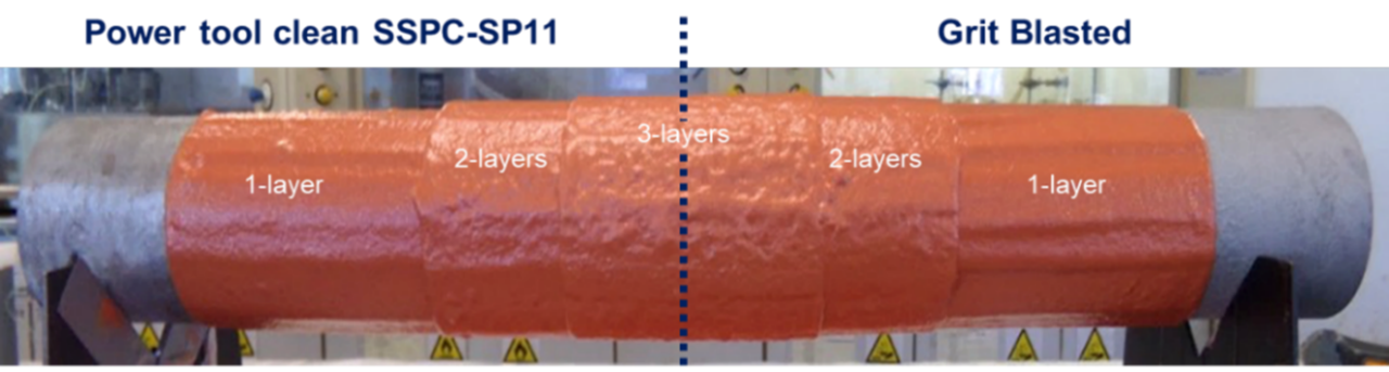
The objective of this test was to subject the epoxy foama to simulated scenarios of multi-phase cyclic CUI and assess its performance based on the possible development of rusting, cracks and/or delamination after exposure. A pipe section constructed of mild carbon steel and of known dimensions was prepared using two different surface cleanliness methods: abrasive blasting to the requirements of SSPC SP 10 and power tool cleaning according to SSPC SP 11. The average profile of both substrates was measured and found to at least average 3 mil and 2 mil for the SSPC SP 10 and SSPC SP 11 substrates, respectively.
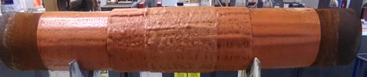
The pipe section was radially encapsulated with the epoxy foam by brush, producing a multilayer finish (consisting of 1-, 2- and 3-layer systems) onto each surface preparation (FIG. 6) and allowed to cure in accordance with the manufacturer’s best practices.
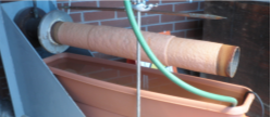
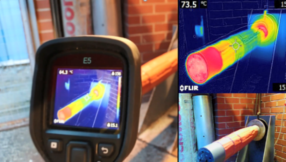
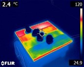
The pipe section was mounted into a designed CUI rig (FIG. 7) and subjected to thermal cycling, as shown in TABLE 4 below. The wet periods consisted of a constant deluge of tap water at a flowrate of 0.26 gal/min from nozzles distributed over the axial extent of the coated piping. Two different regimes, CUI-1 and CUI-2, were scheduled for a total duration of 1,000 hr. The test was monitored via an infrared imaging camera, as shown in FIG. 8.
| Testing regime | Cycle details |
| CUI-1 | Thermal cycle between 248°F (120°C) and 140°F (60°C) with alternating hourly dry/wet periods for 1,000 hr |
| CUI-2 | Thermal cycle between 248°F (120°C) and 50°F (10°C) with alternating hourly dry/wet periods for 1,000 hr |
Upon completion of the test, the proprietary epoxy foama was visually inspected for delamination or cracking. Following visual inspection, the foam was completely removed from the pipe section to reveal the underlying substrate, which was assessed for rusting.
Salt spray (ASTM B117).
The objective of this test was to subject the epoxy foam to a corrosive environment with an intentional scribed line exposing the substrate and to evaluate its performance based on the possible development of cracks and blistering, as well as its ability to resist the creep of corrosion as a result of substrate attack.
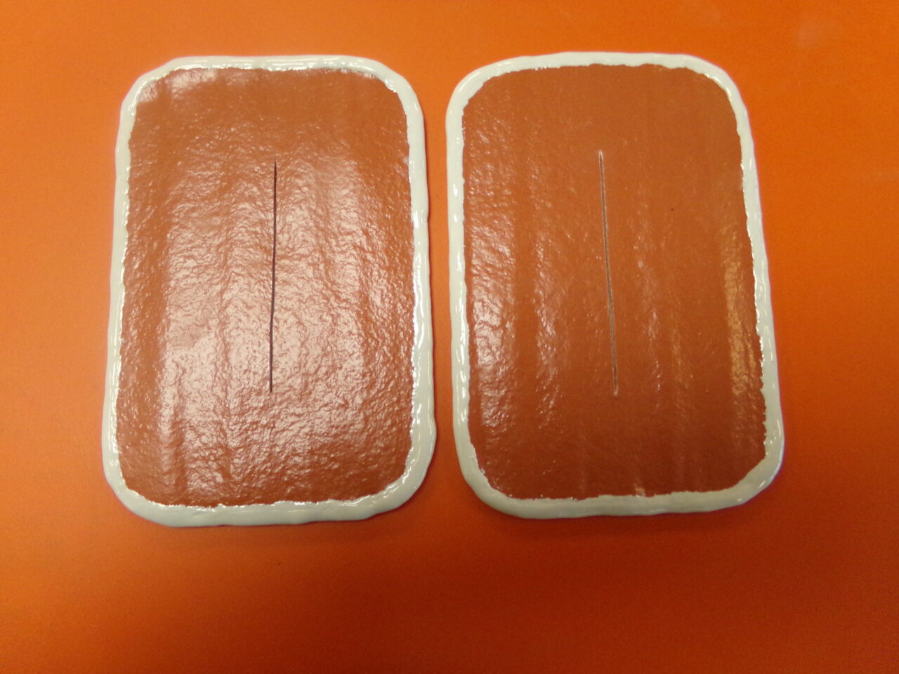
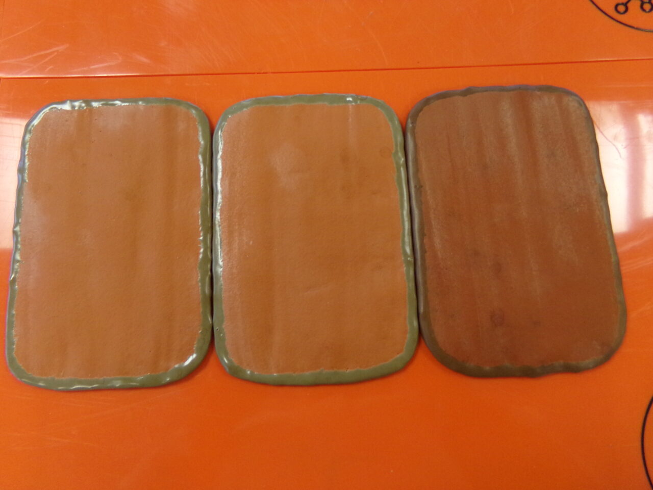
Mild steel panels of known dimensions were prepared to the requirements of SSPC SP 10 with an average substrate profile of 3 mil. The panels were encapsulated with the foam epoxy by 1-layer brush application (FIG. 9). The foam epoxy was cured in accordance with the manufacturer’s best practices. The dry film thickness was measured to be 120 mil. One specimen was cured at 68°F (20°C) while the other was post-cured at 248°F (120°C). A vertical 2-in. scribe line was made in the center line of one side of each panel to expose the underlying substrate and encourage corrosion.
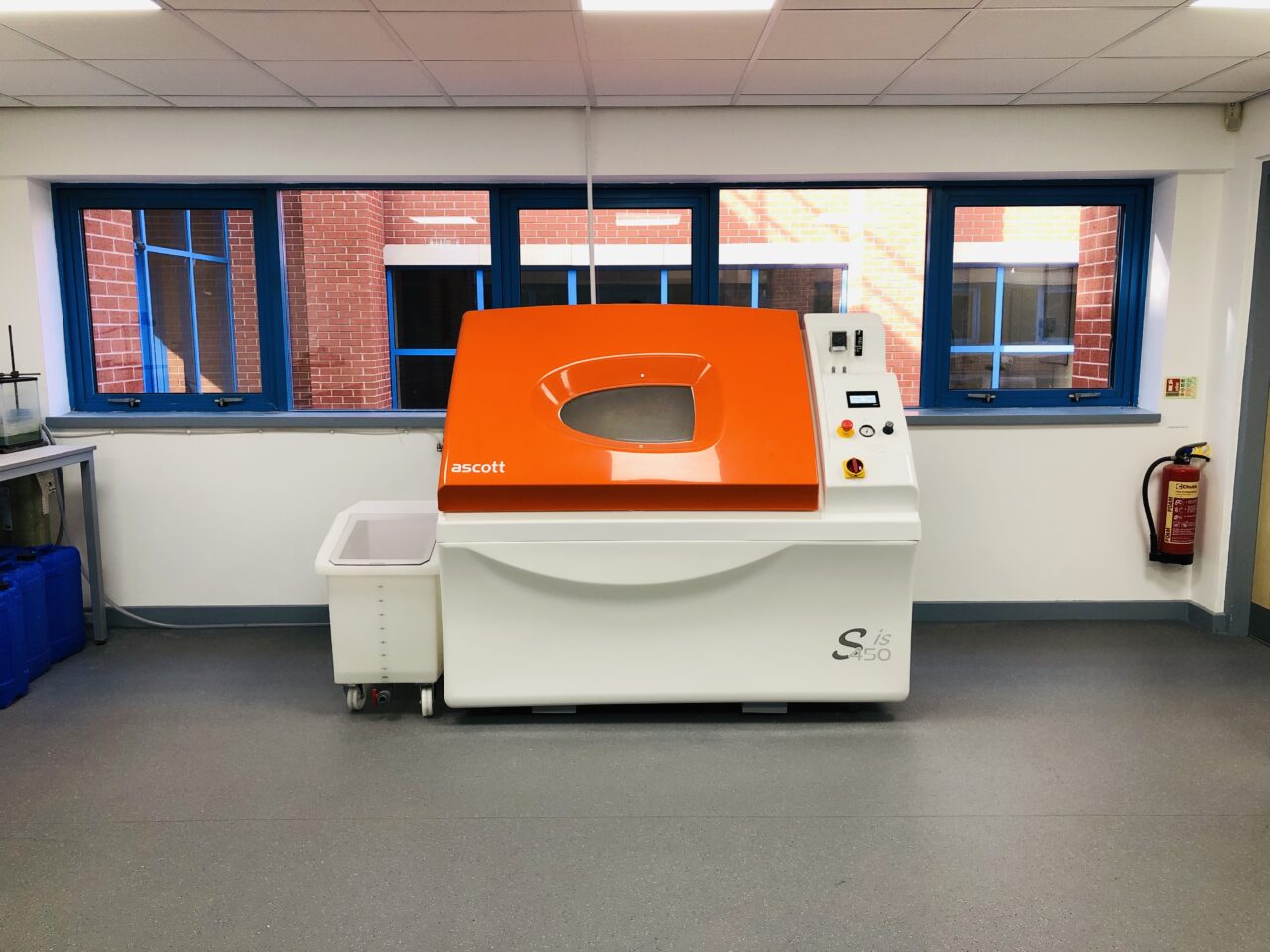
The scribed specimens were positioned in a salt spray chamber operating at 95°F (35°C), as shown in FIG. 10. The coated panels were exposed to this corrosive environment for 4,500 hr. Upon completion of the exposure, the coated panels were visually inspected to assess the integrity of the epoxy foam, which was then completely removed to expose the underlying substrate and assess for corrosion.
Cool-to-touch properties.
The objective of this test was to determine the ability of the epoxy foam to insulate a heated surface by reducing its actual skin temperature to acceptable touch temperatures for contact times longer than 5 sec.
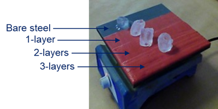
Carbon-steel panels of known dimensions were prepared to the requirements of SSPC SP 10 with an average profile of 3 mil. The panels were partially encapsulated with the epoxy foam using 1-, 2- and 3-coat applications at different wet film thicknesses (WFT) of 25 mil, 40 mil and 120 mil, respectively (DFT is three times WFT), as shown in FIG. 11. The acceptable touch temperature and contact time for the test were set up at 140°F (60°C) and 5 sec, respectively, in agreement with the associated standard and typical regulations set forth for occupational safety 15 in industrial environments. A heater was used as a caloric energy source and a contact thermometer was employed to measure the temperature of both the panel metallic surface and the coated surface (FIG. 12).
The partially coated panels were placed on the hot plate of the heater, set up at 40°F (4.5°C), 194°F (90°C), 248°F (120°C) and 302°F (150°C). The panels were allowed to reach thermal equilibrium before any measurement was taken. The substrate temperatures and thicknesses of the epoxy foam required for achieving thermal reductions below 140°F (60°C) were plotted.
Thermal cycling (ISO 19277).
The objective of this test was to subject the epoxy foam to simulated scenarios of thermal cycling and assess its performance based on the possible development of cracks and/or blisters and delamination after exposure. Three mild steel panels of known dimensions were prepared to the requirements of SSPC SP 10 with an average substrate profile of 3 mil. The panels were encapsulated with the foam epoxy by 1-layer brush application. The applied epoxy was cured at 68°F (20°C) in accordance with the manufacturer’s best practices. The dry film thickness was measured to be 120 mil. The panels were placed in the oven and heated until reaching 248°F (120°C).
Immediately after, the panels were quenched into ice water covering at least ¾ of the test panels and then left immersed until the temperature of the foam epoxy reduced to –22°F (-30°C). This test was repeated for 50 cycles per panel. Specimens were inspected for cracking and delamination.
Pull-off adhesion on substrates cleaned to SSPC 10 and SSPC 11 (ASTM D4541).
The objective of this test was to subject the epoxy foama to pulloff adhesion testing when applied onto substrates prepared to the cleanliness requirements of SSPC SP 10 and SSPC SP 11. Mild steel panels of 400-mil thickness were prepared to the requirements of SSPC SP 10 (by abrasive blasting) and SSPC 11 (by power tool) with an average substrate profile of 3 mil and 1 mil, respectively. The panels were coated with the epoxy foam by 1-layer brush application.
One sample of the epoxy foam per surface preparation method was allowed to ambient cure while the other was post-cured, both in accordance with the manufacturer’s best practices. The epoxy foam applied on each panel was further pulled off and the results compared.
Testing results and discussion.
The range for the epoxy foam was measured to be within 0.03 Btu/ft. h. °F–0.05 Btu/ft. h. °F. Such range of thermal conductivity is comparable to that of vermiculite and silicon dioxide foams, materials used for refractory and insulation purposes in several industries and fireproofing of structural steel and cementitious products. TABLE 5 shows the results at various mean temperatures.
| Sample mean temperature, °F | Thermal conductivity λ / (Btu/ft. h. °F) |
| -40 | 0.0373 |
| -4 | 0.039 |
| 32 | 0.0403 |
| 68 | 0.0418 |
| 140 | 0.0445 |
| 248 | 0.0488 |
| 302 | 0.0505 |
epoxy foama
cracking or delamination were observed in
the epoxy foam. No underlying corrosion was
detected upon foam removal
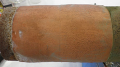
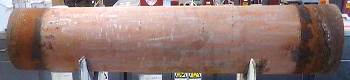
After 1,000 hr of simulated CUI-1 regime testing, coated multi-layer sections on grit-blasted and power tool-cleaned substrates exhibited no failure, as shown in FIG. 13. Neither cracking nor delamination of the epoxy foam were detected. When the insulation was removed by mechanical means, no corrosion was found in the bondline between the substrate and the epoxy foam.
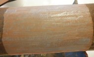
After 1,000 hr of simulated CUI-2 regime testing, coated multi-layer sections on grit-blasted and power tool-cleaned substrates exhibited neither cracking nor delamination of the epoxy foam (FIG. 14). The insulation was mechanically removed. No corrosion was found on the substrate protected with a 2- or 3-layer epoxy foam (FIG. 15). Rust was spotted on the substrate onto which the epoxy foam was applied in 1 layer. This result indicates that the epoxy foam as a 1-layer system should not be recommended for wet service at 248°F (120°C).
After subjecting both samples (ambient-cured and post-cured) to 4,500 hr of spray testing, no delamination or cracking were observed (FIG. 16). Rust developed in the vicinity of the scribed lines, as it can be seen once the foam was removed (FIG. 17).


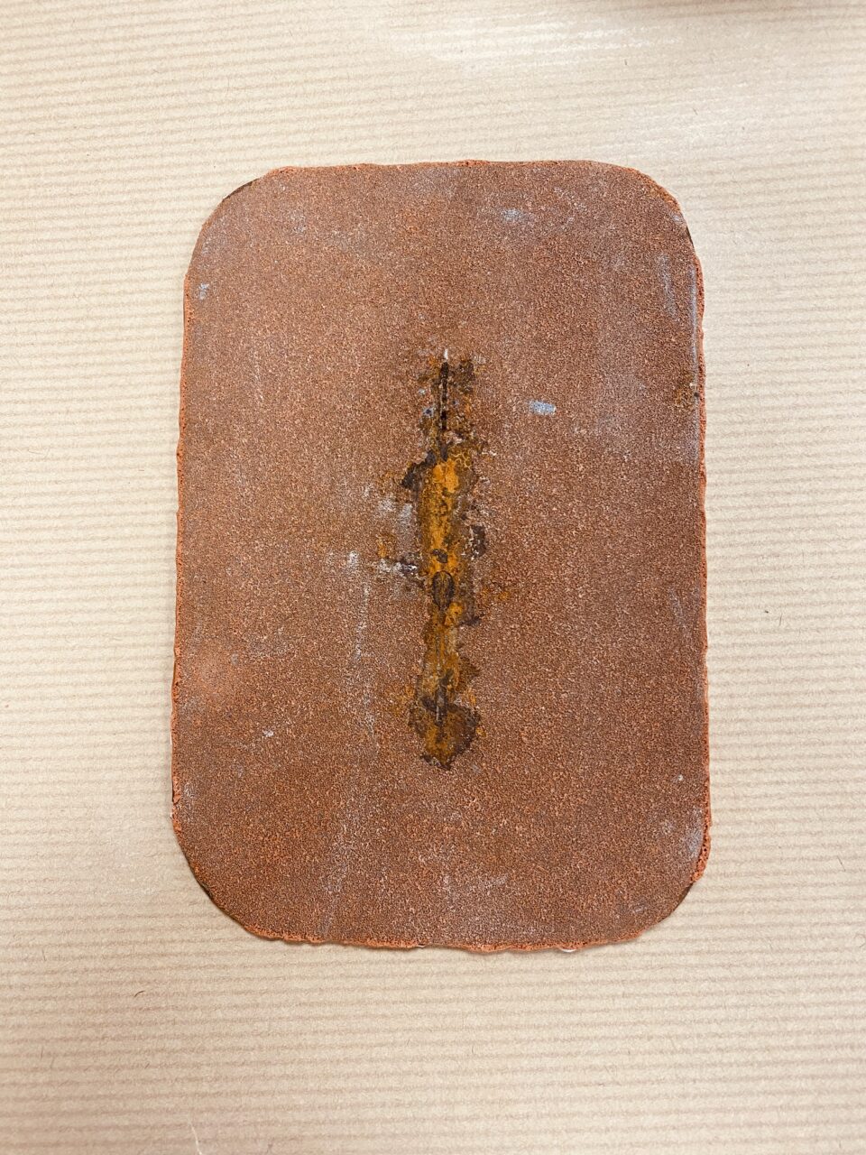
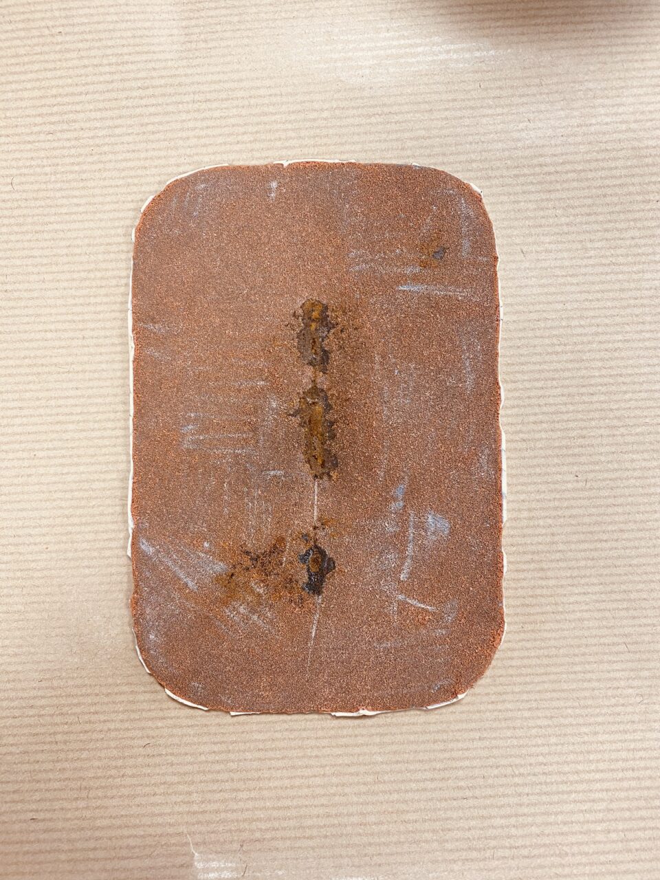
and foam removal (A), and the post-cured
sample after testing and foam removal (B)
The thickness of a 3-coat system of the proprietary epoxy foama was enough to reduce the surface temperature of 302°F to <140°F. Due to the reduction in surface temperature, hand contact can be maintained for longer than 5 sec without burn injuries. Neither cracking nor delamination were observed in any of the panels, as shown in FIG. 18.
| SSPC SP 10 | psi | SSPC SP 11 | psi |
| Ambient-cured | 650 | Ambient-cured | 620 |
| Post-cured | 630 | Post-cured | 680 |
The results can be seen in TABLE 6. In all cases, the epoxy foam resulted in cohesive failure, which implies that the foam was still tightly adhered to the profile when pulled. The surface cleanliness method did not affect the results in any way, which confirms that the epoxy foam is tolerant to minimal surface preparation.
Takeaways.
Several conclusions can be drawn from the development of the epoxy foam. First, the foam uses a solvent-free phenol formaldehyde Novolac epoxy as a base and a polyamine as a solidifier—they react following a typical mechanism of nucleophilic addition to yield a thermosetting polymer. The functionality and chain length of the epoxy resin, solidifier and modified polysiloxane blowing agent are proprietary, but they are used to determine the crosslink density of the foam, and therefore influence its nature, rigidity, closed-cell structure, strength and thermal insulation properties.
Next, the epoxy offers both excellent proven corrosion protection in CUI and water immersion scenarios and thermal insulation, which renders it as an ideal solution for equipment operating at elevated temperatures. It offers safe touch for operators working in hot environments by reducing the surface temperature of industrial assets below 140°F for longer than 5 sec of direct hand contact.
Finally, the epoxy foam offers an array of additional practical features, including ease of application, short-over coat times, durability, tolerance to minimal surface preparation, and quick return to service, among others.
Acknowledgement
This paper was presented by the author or assigned speakers at the Coatings+ 2021 conference.
Note
a BZ5871-EF epoxy foam
References
1 NACE SP0198, “Control of corrosion under thermal insulation and fireproofing materials—A system’s approach,” NACE International, Houston, Texas, July 2017.
2 Lee, S.-T. and N. S. Ramesh, Polymeric foams: Mechanisms and materials, CRC Press LLC, Boca Raton, Florida, May 2004.
3 Domeier, L. and H. Marion, “Epoxy foam encapsulations: Processing and dielectric characterization,” Sandia National Laboratories, SAND99-8213, Livermore, California, 1999.
4 Eaves, D., Handbook of polymer foams, Rapra Technology Ltd., Shawbury, UK, 2004.
5 Singh, S. N., “Blowing agents for polyurethane foams,” Rapra Review Report, Vol. 12, 2002.
6 Pascault, J.-P., et al., Thermosetting polymers, 10th Ed., Dekker, New York, New York, 2002.
7 The Society for Protective Coatings, SSPC-SP 10, “Near-white blast cleaning (NACE No. 2),” 2006.
8 The Society for Protective Coatings, SSPC-SP 11, “Bare metal power tool cleaning,” 2012.
9 British Standards Institution BS EN 12667, “Thermal performance of building materials and products. Determination of thermal resistance by means of guarded hot plate and heat flow meter methods. Products of high and medium thermal resistance,” 2001.
10 ASTM C177, “Standard test method for steady-state heat flux measurements and thermal transmission properties by means of the guarded-hot-plate apparatus,” 2019.
11 International Organization for Standardization ISO 19277, “Petroleum, petrochemical and natural gas industries—Qualification testing and acceptance criteria for protective coating systems under insulation,” 2018.
12 ASTM B117, “Standard practice for operating salt spray (fog) apparatus,” 2019.
13 ASTM C1055, “Standard guide for heated system surface conditions that produce contact burn injuries,” 2020.
14 ASTM D4541, “Standard test method for pull-off strength of coatings using portable adhesion testers,” 2022.
15 ISO 4628, “Paints and varnishes—Evaluation of degradation of coatings—Designation of quantity and size of defects, and of intensity of uniforms changes in appearance—Part 2: Assessment of degree of blistering, Part 3: Assessment of degree of rusting, Part 4: Assessment of degree of cracking,” 2016.

Content Creator, Belzona Polymerics Limited


